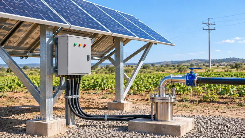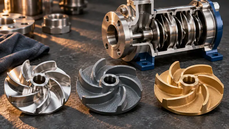
Short answer: To size a borehole pump, define the daily water demand and convert it to flow (m³/h), add static water level + drawdown + delivery height + friction losses to get total dynamic head (TDH), then pick the pump curve whose duty point sits in its best-efficiency zone at that flow and head. Motor power follows from the pump curve, and the well diameter limits the pump size.
Start with the water you actually need
Every correct pump selection begins with demand, not with the pump. Write down how much water the system must deliver per day and over how many pumping hours. A household of five uses roughly 0.75–1 m³ per day; one hectare of drip-irrigated vegetables can need 30–50 m³ per day in peak season; a dairy cow drinks 80–120 litres.
Divide the daily volume by the hours the pump will run. Twenty cubic metres per day over 8 hours means a design flow of 2.5 m³/h. If the pump feeds a pressure tank or drip network directly, use the peak instantaneous demand instead — for example the number of sprinklers running at once multiplied by their flow.
Check what the borehole can give
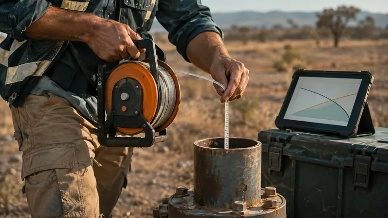
A pump can never deliver more than the aquifer supplies. Your drilling report should state the static water level, the tested yield and the drawdown at that yield. Never select a pump with a flow above about 80% of the tested yield; doing so drags the water level down to the pump inlet and causes dry running.
- Static water level – depth to water when nothing is pumping.
- Drawdown – how far the level drops while pumping at the test rate.
- Dynamic water level – static level plus drawdown; this is the real starting point for head.
Calculate total dynamic head (TDH)
Head is height. A pump curve is plotted in metres of head against flow, so all your losses and lifts must be converted to metres:
TDH = dynamic water level + elevation to outlet + outlet pressure (bar × 10.2) + friction lossesFriction losses depend on pipe diameter, length and flow. As a field rule, PE or uPVC pipe sized so that water travels at 1–1.5 m/s loses roughly 2–4 m of head per 100 m of pipe; add about 10% for valves and fittings. Undersized pipe is the most common reason a correctly chosen pump under-performs.
A worked example
| Item | Value |
|---|---|
| Daily demand | 20 m³ over 8 h = 2.5 m³/h |
| Static water level | 35 m |
| Drawdown at 2.5 m³/h | 8 m |
| Tank on a 6 m stand, 15 m above wellhead | 15 m |
| Friction: 180 m of 40 mm PE + fittings | ≈ 7 m |
| Total dynamic head | ≈ 65 m |
We now need a pump delivering 2.5 m³/h at 65 m. In our range that points to a 4-inch multistage pump such as the 4SDM4/12 family, whose curve passes through that duty point near its best efficiency zone. A 3-inch alternative exists if the casing is narrow, but it will typically need more stages and a slightly larger motor.
Estimate motor power
Hydraulic power is easy to compute and is a good sanity check against catalogue data:
P (kW) = Q (m³/h) × H (m) ÷ (367 × η)With 2.5 m³/h, 65 m and a realistic wire-to-water efficiency of 45% for a small 4-inch pump, P ≈ 0.98 kW. The nearest standard motor is 1.1 kW (1.5 HP). Always confirm against the manufacturer's curve; small pumps have lower efficiencies than large ones, and solar DC pumps can be considerably more efficient at the same duty.
Cable, voltage and starting
Voltage drop along a long drop cable starves the motor and shortens its life. Keep total voltage drop below 3–5%. For single-phase 220 V motors above 1.5 kW or cable runs over 100 m, three-phase supply or a larger conductor size is usually the better answer. Three-phase pumps above 4 kW should use a soft starter or VFD to reduce hydraulic shock and inrush current.
Installation details that protect the pump
- Hang the pump at least 3–5 m below the dynamic water level and 2–3 m above the well bottom.
- Fit a non-return valve every 60–80 m of vertical rising main on deep installations.
- Use a dry-run or level probe protection relay — especially in low-yield wells.
- Add a cooling sleeve if the pump sits below the screen or the casing is much larger than the motor.
Quick selection checklist
- Daily volume and pumping hours → design flow.
- Borehole report → dynamic water level and maximum safe flow.
- Elevation, pressure and friction → TDH.
- Pump curve → duty point in the efficient zone.
- Casing ID → 3", 4" or 6" pump.
- Power supply → single-phase, three-phase or solar.
Send us those six numbers through the inquiry form and our engineers will return a curve-matched recommendation, usually within one working day.
Frequently asked questions
What is total dynamic head (TDH)?
TDH is the total height the pump must lift water, expressed in metres. It equals the dynamic water level (static level plus drawdown), plus the vertical rise from the wellhead to the delivery point, plus pressure required at the outlet (10 m per bar), plus friction losses in pipes and fittings.
How much bigger should the pump be than my calculation?
Choose a pump whose duty point sits near the middle of its curve rather than adding a large safety margin. Oversizing by more than 10–15% wastes energy, increases wear and can pull the water level below the pump inlet.
Will a 4-inch pump fit in a 4-inch borehole?
Usually yes — a 4-inch pump has an outside diameter of about 98–100 mm and is designed for casings with an internal diameter of at least 101 mm (4"). Allow clearance for the flat cable and cable guard; a 4.5" to 5" casing is more comfortable.